Project Description
Category: Testing
Description: Dismountable faceplate
Materials: Carbon and alloy steel
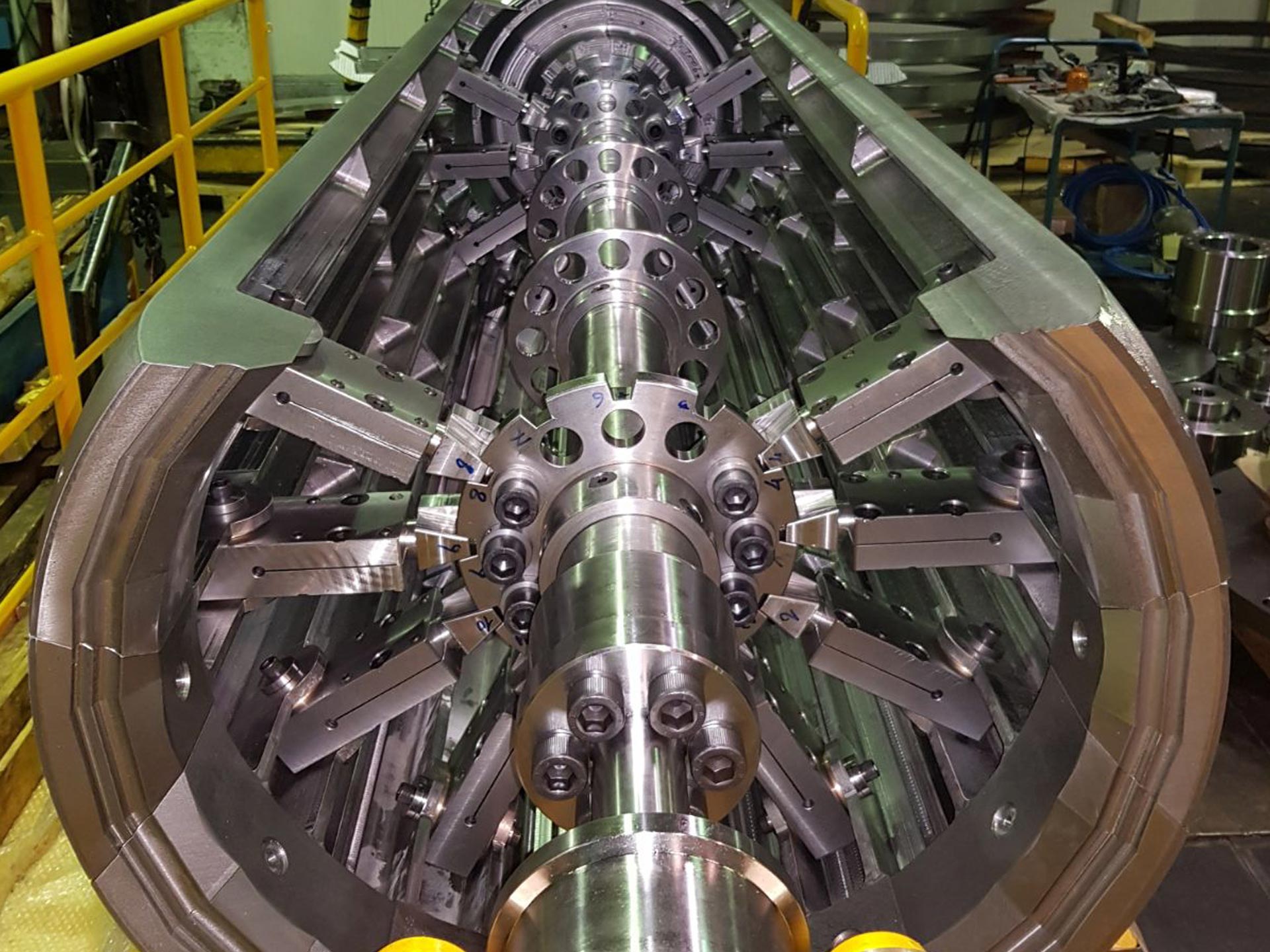
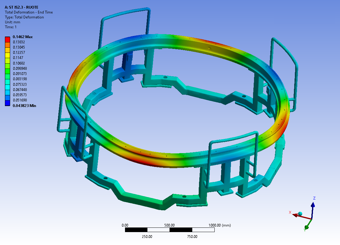
The winding faceplate is composed of a central shaft, i.e. a central axle in lathe-turned structural tubing where removable sections are coupled and, on complete assembly, including the covers, act as a counter-mould for the winding phases of the motor casing. The casing to mould has a diameter of 850mm and is 2400mm long.
The wall of the counter-mould is composed of 12 sections (6 with a spanner function and 6 with a counter spanner function), profiled externally to achieve the necessary shape. The sections are held in position by a series of connecting rods that connect them to the central shaft.
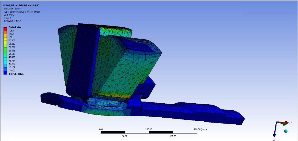
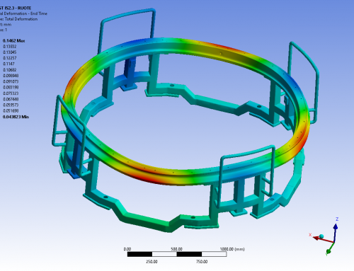
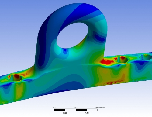
Everything is designed for easy assembly and to allow the dismantling of restrained mechanisms/kinematics, dismantling from inside and passage of the single part, including the appendages for the extraction hole with a diameter of 280mm on the nozzle side, but especially to guarantee structural stability and shape during the winding phases under the load generated by composite material pressure in the treatment processes and under the effect of the treatment temperature.
The ends of the central shaft require the necessary machining and flanges for coupling of the extensions and shafts for the interface, with the various production process machinery of the motor.
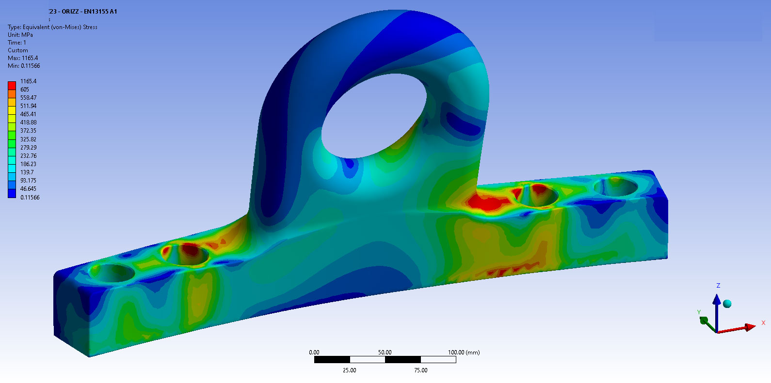
The assembly phase takes place horizontally using a dedicated station on which the support saddle, the rotation cradle and the overturning bracket of the faceplate are fastened. This structure is similar to a semi-machine, which is stabilised on 4 parking feet during the use phase and equipped with its own wheels. It can be moved by an overhead crane using the specific eyebolts or using an electric pallet truck.
The two end cradles differ from one another: in particular, the cradle on the starter side allows the shaft to be grasped by its shank, rotating it around its axis via a manual gearmotor; it can tilt, to allow vertical overturning of the faceplate and has an interface flange for temporary support of the cover. The cradle on the nozzle side allows rolling of the shaft on the support saddle and can be overturned. The intermediate cradle is instead planned to support the faceplate by the shank and is manufactured with a pantograph mechanism that allows its ascent and descent.
The design is completed with a technical platform. This is composed of an independent metal structure to install inside the work premises, with a hard support shell in commercial, structural profiles anchored to the foot. The usable surface, with a surface capacity of 500daN/m2, has a central hole with suitable dimensions for safe passage of the wound casing and guarantees a work corridor of at least 1.50m all around the central hole. The perimeter of the central hole has a fixed safety footguard, a plastic slide to avoid impact with the overhead crane during the manoeuvre phase damaging the casing created and a safety plug (normally closed in the absence of a casing).